Geophysical Methods and Modelling for Geohazards characterization
Described here is work related to shear wave profiling, surface wave data, wavelet transforms to infer excess pore pressures and basin modeling.
Shear wave profiling
Conventional P-wave seismic data are paramount to obtaining a detailed image of the shallow subsurface where most offshore geohazards occur. However, P-waves are not suited to extract geotechnical information, such as shear strength, in the absence of boreholes. P-waves sense both the solid matrix and the pore fluids. On the other hand, shear waves are primarily influenced by the matrix and, to a lesser degree, by pore fluids.
Despite the more complicated data acquisition and processing techniques, shear wave data have several advantages over P-wave data, e.g., the possibility to "see" through gas clouds, lithology and fluid discrimination, and overpressure quantification (shallow water flows). Even though S-wave velocity increases rapidly in the shallow subsurface, their values are still low compared to P-wave velocities. This suggests that S-wave data have a higher vertical resolution, even though the typically lower quality factor for S-waves offsets this somewhat.
ICG activities on this level are two-fold
First, NGI developed a prototype seabed-coupled shear wave vibrator with flexible polarization direction, which was used at specific locations in the North Sea in collaboration with Statoil (Figure 7). Combined with conventional airguns and coupled ocean-bottom cables, this would allow recording the full seismic wavefield. Part of the processing, particularly the surface wave part (see underneath, under publications), was taken care of by ICG. Shear wave data analysis is complemented with NGI's in-house full-waveform simulations LaySac (Figure 8).
Second, in collaboration with LIAG (Hannover) and ICG-Theme 1, a dedicated land 2.5D shear wave survey was conducted in the harbor of Trondheim, an area claimed for the sea and undergoing active subsidence, close to landslide features documented in the fjord. A shear wave vibrator and specially-designed geophone cable were used to acquire in SH mode, courtesy of LIAG. The multi-channel data are fully processed at ICG (Figure 9). The final processing step, pre-stack depth migration, is currently undertaken (Sauvin et al.).
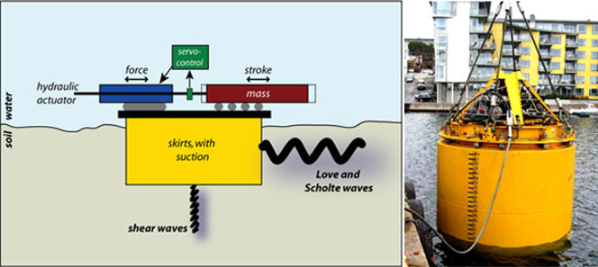
Figure 7: Sketch and picture of NGI's prototype shear wave vibrator for seabed-coupled surveying
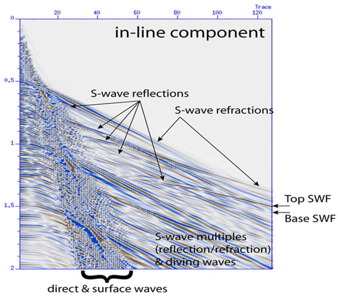
Figure 8: Full waveform synthetic seismic data (acceleration) simulating the seismic response of an overpressured zone (shallow water flow) at about 175 m below the surface, using a seabed-coupled shear wave Source.
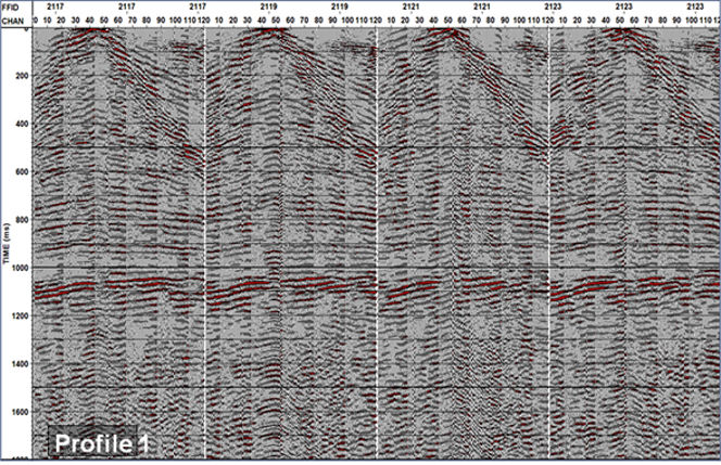
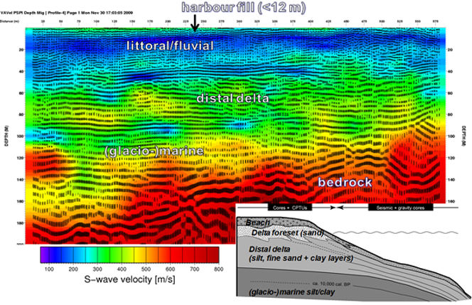
Figure 9: Example of shear wave shot gathers (top) and processed (post-stack depth migrated) section with colour-coded shear wave velocity. The sketch illustrates the relationship between the onshore and offshore geophysical data.
Surface wave data
Using the geometrical dispersion that characterizes surface waves (i.e., phase velocity becomes frequency or wavelength dependent) allows for determining the shear wave velocity of the shallow sub-surface in great detail. To this end, surface wave data are typically recorded by a linear array of closely spacing geophones/seismometers, using a vibrator, impact source, sledgehammer, or dropping a sandbag as a source.
Most energy generated will be emitted as surface waves that penetrate about half a wavelength down in the sub-surface. Whereas all the wavelengths travel through the top part, only a few penetrate to larger depths, leading to a mix-determined problem. The wave equations yield a discrete number of solutions for surface wave modes at a given frequency: the fundamental and higher surface wave modes. Dependent on the source and receivers, either Rayleigh/Scholte waves or Love waves are detected, with the former being a combination of P- and SV-waves and the latter solely SH-waves trapped.
The marine shear wave data revealed several higher surface wave modes of Scholte and Love polarizations, a unique seismic data set. These were subsequently used to invert for a shear wave profile with depth in collaboration with Politecnico di Torino (Figure 10). The data were further used to fine-tune and validate NGI's internal multi-modal surface wave inversion code, which is based on an optimized curve-fitting routine and Marquardt-Levenberg algorithm, and which inverts for both shear wave velocity and layer thickness (Figure 11). Other surface wave tools available at ICG are the swami code (Rix and Lai), Geopsy (Wathelet), and SurfSeis (KGS), as well as in-house MatLab/Octave routines.
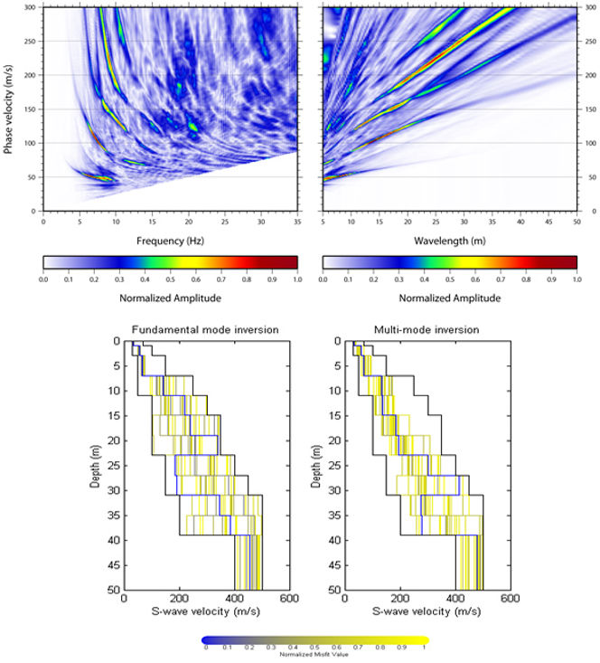
Figure 10: (Top) Multi-modal Love surface waves obtained using a densely populated effective OBC and NGI's prototype shear wave vibrator at the Gjøa field, North Sea; (bottom) Resulting shear-wave velocity profile from inversion (Vanneste et al., Socco et al., in press).
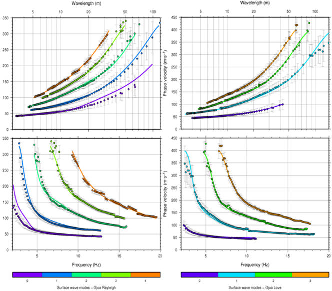
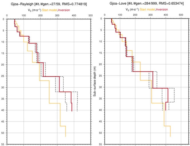
Figure 11: Results from NGI's multi-modal surface wave inversion algorithm. (Top) Multi-modal Scholte/Rayleigh data (dots) and best-fit forward models (lines); (bottom) Resulting shear-wave velocity profile from inversion.
Can wavelet transforms be used to infer excess pore pressures?
High-resolution seismic reflection data from part of Finneidfjord are characterized by a distinct shallow gas front overlying a zone of intense amplitude attenuation (Figure 12). The quality factor of a medium expresses how well a medium propagates seismic energy, here P-wave, and is composed of intrinsic attenuation and scattering. The presence of free gas effects causes both intrinsic attenuation and scattering, and the frequency-dependence of partially-saturated soils can be analyzed through continuous wavelet transforms (Li et al., Geophysics, 2006), which yields improved time-frequency characterization and localization, compared to Fourier or Gabor transforms.
This technique was successfully applied to synthetic data generated with NORSAR2D, and translated to the Finneidfjord case study using a Mexican Hat Wavelet. The two horizons picked were the gas front and a peak interpreted to correspond with somewhat coarser material. The inversion scheme by Carcione & Picotti (Geophysics, 2006) is further used for pore pressure and calibrated with in situ piezometer data acquired on-site (Morgan et al., 2009). This ongoing work needs further fine-tuning and QC. This work furthermore heavily depends on accurate physical properties of the soils, i.e., another reason why high-quality sampling is paramount.
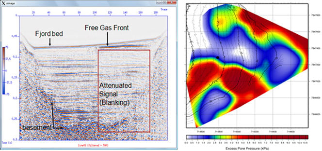
Figure 12: Excess pore pressure estimated at the top of the shallow gas accumulation in Finneidfjord, from inversion of seismic amplitudes after wavelet decomposition and rock physical models.
Basin modeling
Modeling the generation and migration of excess pore pressure provides essential slope stability and risk assessment information. Basin2 (now obsolete) was used at NGI/ICG to investigate pore pressure development within the North Sea Fan (NSF), off south Norway (Figure 13). An extensive glacial fan has accumulated in this area, located off the mouth of the Norwegian Channel. Loading of the soils by the infill of glaciogenic debris flows during peak glacial times and subsequent lateral excess pore pressure migration is believed to have played a vital role in the Storegga Slide about 8200 years ago.
Modeling has indicated that, at present, excess overpressures still exist within the NSF, but the magnitude has decreased compared to peak glacial conditions. It must be stressed that site-specific soil profiles should be used in basin modeling, as default soil profiles do not necessarily represent the soil conditions adequately. The source code of Basin2 is still available at NGI, and will be extended to use improved relationships based on laboratory testing at the given site under investigation.
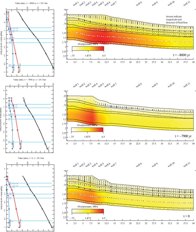
Figure 13: Modelling of pore pressure evolution for the NSF can study, using Basin2
