Tsunami modeling
Up to now, initial seafloor displacements resulting from tsunami-triggering earthquakes are calculated using a simple, analytical method (e.g., Okada's method; Okada, 1992, BSSA) in most oceanographic models analyzing tsunami inundation heights at neighboring coastlines.
Although analytical solutions are mathematically exact and inexpensive regarding computation powers, they only allow for simple model geometries and homogeneous material properties. Geist and Dmowska (1999, PAGEOPH) state that the effects of heterogeneous slip patterns on the earthquake fault plane are essential to include in the local tsunami wave field.

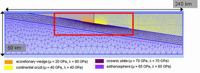
Figure 9. Inhomogeneous FEM mesh used to calculate seafloor displacement resulting from slip on earthquake faults; mesh is subdivided to represent accretionary wedge, continental crust, oceanic plate and asthenosphere
The amount of slip for a given seismic moment depends not only on fault plane properties, e.g., the distribution of asperities but also on the shear modulus of the surrounding material, which may vary with depth in subduction zones from 3 to 30 GPa (Bilek and Lay, 1999, Nature). The curvature of the fault plane and seafloor topography may additionally influence the resulting displacement pattern. Such inhomogeneities can only be captured by a numerical model.

Figure 10. Influence of change of subduction angle from 0° to 90°; left: vertical displacement, right: horizontal displacement, light colour: steep subduction angle, dark colours: shallow subduction angle.
We use the FEM numerical method to deal with surface displacement computations resulting from slip on a fault. GeoFEST (Jet Propulsion Laboratory at California Institute of Technology; authors: G. Lyzenga and J. Parker) was chosen to be the most appropriate software solution for our task, since the code is capable to account for material inhomogeneities, a heterogeneous slip distribution on the earthquake fault plane and irregular fault geometry in 2-D or 3-D. Further, it is possible to include multiple faults, seafloor topography, and friction on the fault.

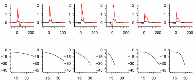
Figure 11. Influence of change fault plane bending; top: vertical displacement (red: bended fault plane, black: comparison to homogeneous model), bottom: sketch of bended fault plane.